Mechanical Engineer, Manufacturing Engineer
Jason Moore
ANALYSIS/DESIGN
-
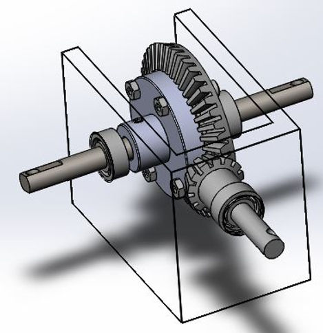
Approach: The approach to this design consists of considering how many gear reductions are needed and how much space the drivetrain can take up. It was previously determined that there will be two gear reductions.The first step of the design is to take the input speed of the motor and apply a gear reduction to a driveshaft.The next step is applying the final gear reduction from the drive shaft to the rear output shaft.
-
Calculated Parameters: One of the biggest parameters of the design is the space available. The drivetrain needs to be small and compact as there are other components that need to be attached to the chassis. Because of this, bevel gears are needed to change the direction of the output to allow for the optimization of space.
-
Device Shape: The chassis is long and narrow which is why space is limited. With the use of a drive shaft, the bevel gears can be arranged in a manner that will take advantage of the available space.
-
Tolerances, Kinematics, Ergonomics: The tolerances for the gear train need to be fairly precise to allow for proper operation and to prevent interference which may result in binding and also to prevent excessive backlash. Some of the kinematics include the forces acting on the gear teeth, drive shaft and the secondary shaft that will be supported with bearings.


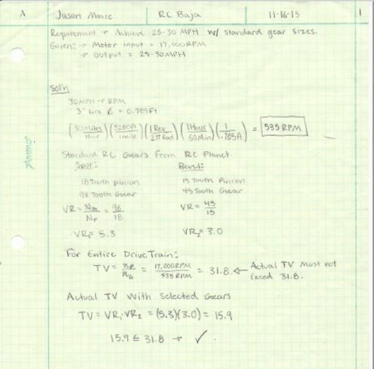


Calculations
The following documents are just some of the calculations performed for the drivetrain. This project required alot of analysis including gear kinematics, rotational to linear velocity conversions, pitch diameter, center distances, pitch line speed, transmitted loads, bending and contact stresses, max bending stress, vertical shear stress and torsional shear stress. To save time, several different "calculator spreadsheets" were created in Excel so one could simply provide a few inputs to get many different outputs or solutions.