Mechanical Engineer, Manufacturing Engineer
Jason Moore
Construction
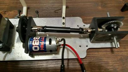
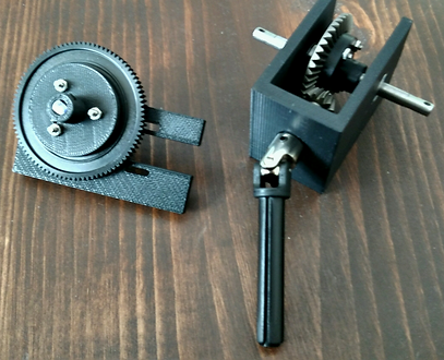
The drivetrain will consist of mainly two sub-assemblies. The first sub-assembly will consist of the spur gear reduction and the second sub-assembly contains the bevel gear reduction.
-
Both sub-assemblies will have some parts that are made and some parts that are bought. The student engineer will produce the mounts for the motor, gear adapters and output shafts. The driveshaft, gears and bearings will be designed to standard and then purchased from an appropriate vendor.
-
The resources needed to produce the necessary components in these sub-assemblies include the rapid prototyping machine, milling machine, drill press and various hand tools. Most of the components were printed on the 3-D printer with the exception of the two steel shafts. The shafts had to be machined on a mill. The hardest part about this process was determining how to secure the work on the mill in a manner that would allow the engineer to apply the necessary cuts. After some time, a three jawed fixed chuck was used.
-
The motor mount is one of the most crucial elements of the entire drivetrain. This is because the location of the holes for the motor shaft and the gear shaft must be a specific distance away from each other to allow for proper meshing of the gears (center distance). Since the student engineer will be manufacturing this part, constant monitoring of dimensions will be crucial. The bevel gear mount is also a crucial component for similar reasons. If the mount is to successfully allow the rear bevel gears to mesh for proper power transmission then these dimensions must also be monitored during the machining process.
-
Manufacturing issues: The major manufacturing issue was time. The entire car had to be built and tested by April. This is why most of the tasks on the schedule don’t exceed past March.
Other than time, there were issues with some of the 3-D printed parts in the steering and suspension systems. The All-Mount sheared twice where the A-arms connect to it. This was after the dimensions and geometry had been redesigned to produce the most strength for the available room. After some investigation, it was determined that the 3-D parts were full of small voids where they sheared and it was realized that the prototyper could not be used to produce the parts that were needed. Instead, an aluminum replacement part was machined and installed and is sufficient. This was the major issue that occurred simply because it kept happening and it pushed the testing back a week.
Another general issue that manifested was simply working with plastic parts. Some plastic parts, both printed and purchased, had to be machined. The issue is that plastic parts are not very rigid which made machining rather difficult in some cases particularly with thinner plastic parts such as the spur gear in the front gear reduction.